Design of materials microstructure by 3-D image-based mechanical simulation using high-resolution X-ray CT
問い合わせ番号
SOL-0000004513
ビームライン
BL20B2(医学・イメージングI)
学術利用キーワード
| A. 試料 | 無機材料, 計測法、装置に関する研究 |
|---|---|
| B. 試料詳細 | 金属・合金, 絶縁体・セラミックス, 結晶性固体 |
| C. 手法 | 吸収、及びその二次過程 |
| D. 手法の詳細 | 反射、屈折 |
| E. 付加的測定条件 | 三次元画像計測(CT等), 室温, 時分割(比較的遅い) |
| F. エネルギー領域 | X線(4~40 keV) |
| G. 目的・欲しい情報 | 局所構造, 欠陥、転位、歪み, 構造変化, 形態・巨視的構造 |
産業利用キーワード
| 階層1 | 機械, 金属, 工業材料 |
|---|---|
| 階層2 | 構造材(鉄、非鉄) |
| 階層3 | |
| 階層4 | 亀裂、空隙, 内部構造, 形態 |
| 階層5 | イメージング |
分類
A80.20 金属・構造材料, A80.30 無機材料, M60.20 X線CT
利用事例本文
In-situ material tests using a synchrotron X-ray CT are new methods to observe fracture behavior of microstructures in materials. The methods are useful to take 3-D sequential images of such fracture behavior. At the beamlines BL47XU and BL20B2, the high-resolution CT system is available to perform 3D high-resolution imaging and sequential observations using an in-situ test rig.
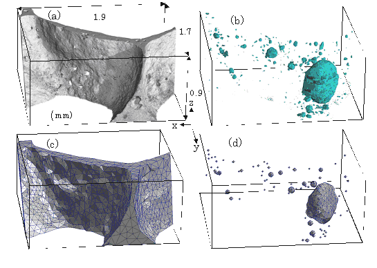
Figure illustrates how an analysis model was created from part of the whole tomographic volume. The polygonal model in the Fig.(c) was extracted from the external form of the cell wall in the aluminum foam in Fig.(a) by a trilinear interpolation. Also the polygonal models of the micropores in Fig.(d) were similarly extracted from the volume in Fig.(b). The methods demonstrated in this study can apply the damage of various materials as well as metals and damage mechanism such as destruction with considerable accuracy can be specified.
画像ファイルの出典
原著論文/解説記事
誌名
H. Toda, M. Takata, et al. Adv. Engng. Mater. (2006), submitted.
図番号
測定手法
画像ファイルの出典
図なし
測定準備に必要なおおよその時間
1 シフト
測定装置
| 装置名 | 目的 | 性能 |
|---|---|---|
| X-ray CT system | obtain 3D structure of materials | spatial resolution of about 10um |
参考文献
| 文献名 |
|---|
| H. Toda, M. Takata, et al. Adv. Engng. Mater. (2006), submitted. |
| H. Toda, N. Kuroda, et al., Proc. XRM2005, (2005), submitted. |
関連する手法
アンケート
SPring-8だからできた測定。他の施設では不可能もしくは難しい
本ビームラインの主力装置を使っている
測定の難易度
初心者でもOK
データ解析の難易度
中程度
図に示した全てのデータを取るのにかかったシフト数
2~3シフト


