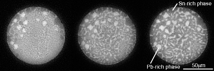
Three-dimensional observation of micro structure evolution in micro-solder balls
問い合わせ番号
SOL-0000000934
ビームライン
BL47XU(マイクロCT)
学術利用キーワード
| A. 試料 | 無機材料 |
|---|---|
| B. 試料詳細 | 金属・合金, 誘電体・強誘電体, 絶縁体・セラミックス, 結晶 |
| C. 手法 | 吸収、及びその二次過程 |
| D. 手法の詳細 | |
| E. 付加的測定条件 | 三次元画像計測(CT等), 時分割(比較的遅い) |
| F. エネルギー領域 | X線(4~40 keV) |
| G. 目的・欲しい情報 | 欠陥、転位、歪み, 構造変化, 形態・巨視的構造 |
産業利用キーワード
| 階層1 | 半導体, 電子部品, 機械, 金属 |
|---|---|
| 階層2 | シリコン系半導体 |
| 階層3 | 配線 |
| 階層4 | 密度, 内部構造 |
| 階層5 | イメージング |
分類
A80.10 エレクトロニクス, A80.12 半導体・電子材料, A80.20 金属・構造材料, A80.30 無機材料, M60.20 X線CT
利用事例本文
Micro-tomography is a powerful technique to study internal structures of materials. Using this technique, one can measure the micro structures of microjoinings on PCB (Printed Circuit Board). The distribution of the constituent phases in Sn-Pb eutectic solder was identified based on the estimation value of X-ray linear attenuation coefficient. And the phase growth process due to cyclic thermal loading was determined by the observation of the CT images obtained consecutively at the fixed point of the target joining. The figure shows the CT images of same solder ball at the different time (after the heat loads). These data reveal the micro-tomography can be used for evaluation of fatigue lifetime of micro joinings.
[ T. Sayama, H. Tsuritani, K. Uesugi, A. Tsuchiyama, T. Nakano, H. Yasuda, T. Takayanagi and T. Mori, Proceedings of 11th Symposium on "Microjoining and Assembly Technology in Electronics" 11, 189-194 (2005), Fig. 7,
©2005 Japan Welding Society ]
画像ファイルの出典
原著論文/解説記事
誌名
エレクトロニクスにおけるマイクロ接合実装技術シンポジウム論文集, Vol. 11 (2005), pp. 189-194.
図番号
fig7
測定手法
画像ファイルの出典
図なし
測定準備に必要なおおよその時間
3 シフト
測定装置
| 装置名 | 目的 | 性能 |
|---|---|---|
| X-ray CT system | obtaining internal structures of materials | spatial resolution of about 1µm |
参考文献
関連する手法
アンケート
SPring-8だからできた測定。他の施設では不可能もしくは難しい
本ビームラインの主力装置を使っている
測定の難易度
初心者でもOK
データ解析の難易度
中程度
図に示した全てのデータを取るのにかかったシフト数
2~3シフト


